
- 全部
- Basic Information
- Installation & Environment
- Operation & Usage
- Parameter Settings
- Troubleshooting
- Maintenance & Safety
- Other FAQs
How to Replace Ink for Small Character Inkjet Printer?
Refer to the video below for detailed steps.
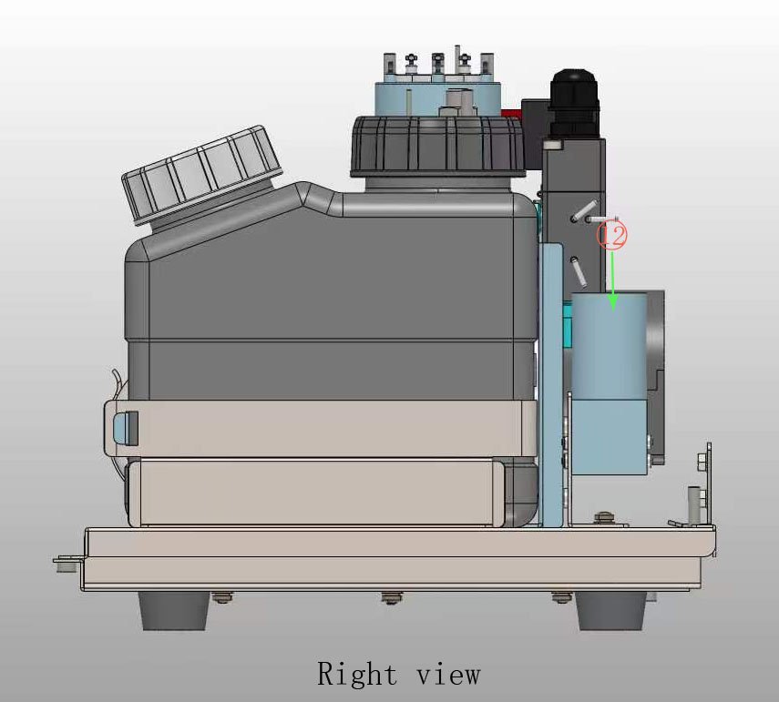
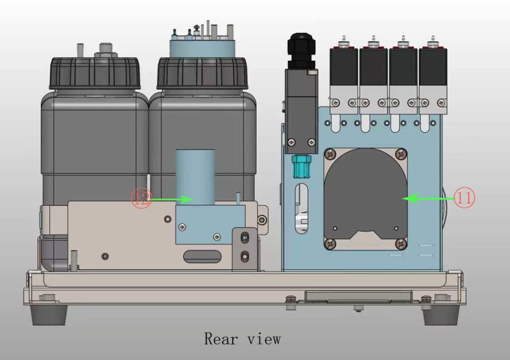
Introduction to Main Components of Ink Circuit System
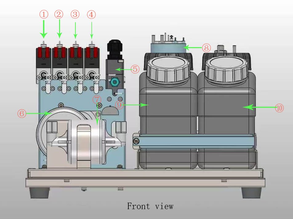
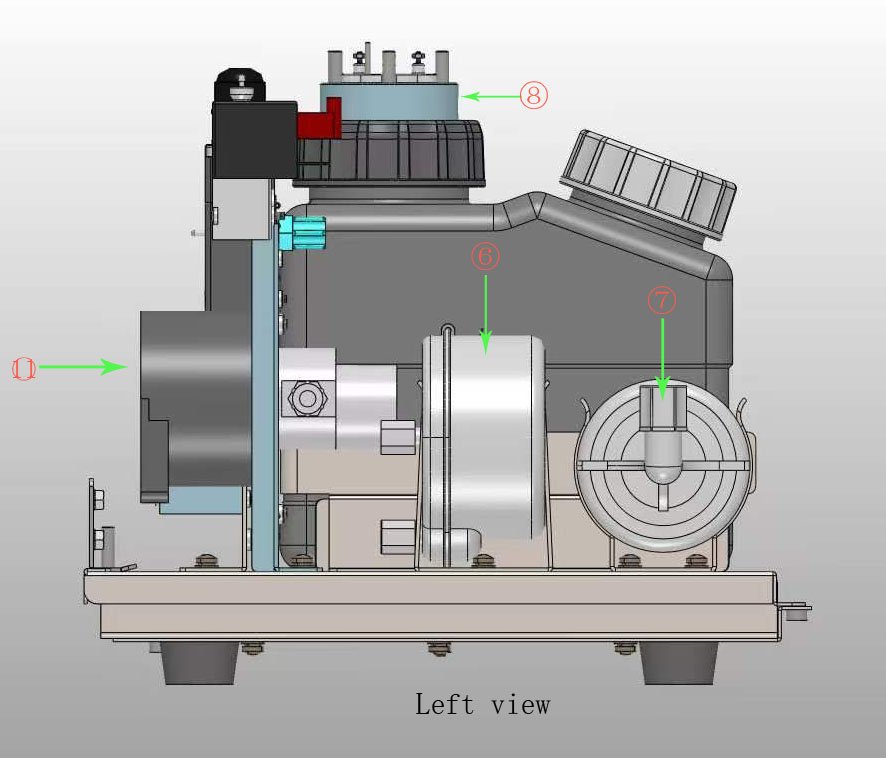
①Cleaning Valve
②Recovery Valve
③Solvent Valve
④Viscosity Valve
⑤Venturi
⑥Buffer
⑦Filter
⑧viscosity pot
⑨Ink Tank
⑩Solvent Tank
⑪Ink Pump
⑫Cleaning pump
Solutions for Common Faults of Early-Version Printheads
Below are the handling solutions for frequent faults of early printheads. Click the corresponding items to view detailed operation procedures:
1.Solution for Ink Leakage of Recovery Tube (See link below)
https://rpz-sp.com/faq/solutions-for-ink-leakage-of-recovery-tube/
2.Solution for Abnormal Phase Signal Display of Inkjet Printer (See link below)
https://rpz-sp.com/faq/solution-for-abnormal-phase-signal-display-on-old-version-inkjet-printers/
3.Solution for Ink Leakage at Recovery Tube Joint (See link below)
https://rpz-sp.com/faq/solution-for-ink-leakage-at-recovery-tube-joint-of-old-version-printheads/
Solution for Abnormal Phase Signal Display on Old-Version Inkjet Printers
Applicable Note
This abnormal phase signal failure only exists in old-version machines. The circuit design of new-version equipment has been optimized, and this modification is unnecessary.
Modification Steps
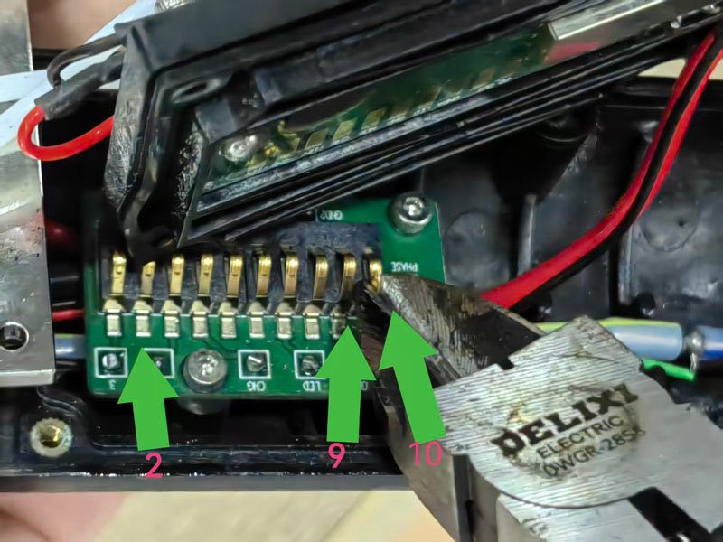
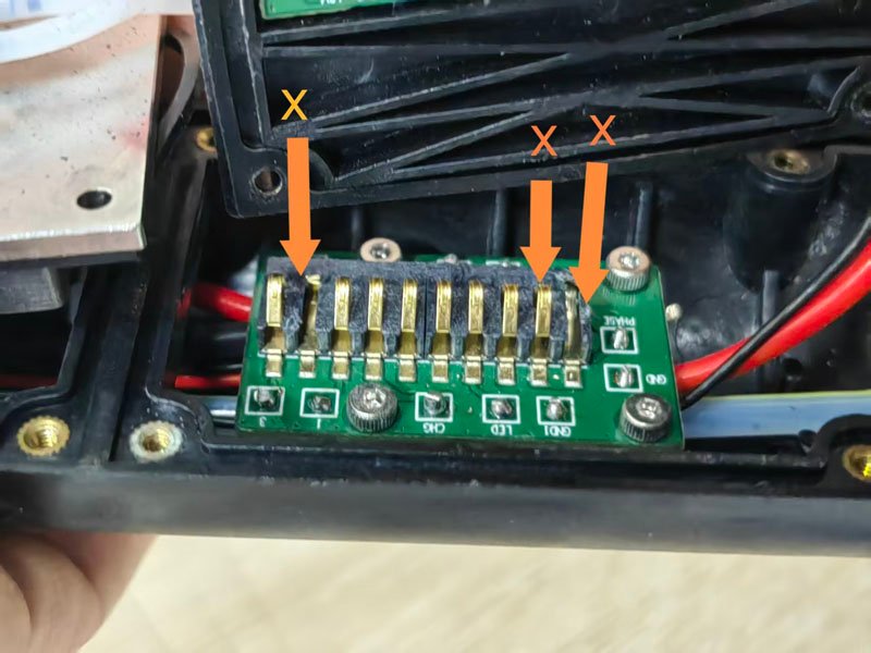
1.Disassemble the printhead and trim the 2nd, 9th and 10th metal contacts on the lower circuit board flat.
2.Unscrew all fixing screws of the lower circuit board and remove the board.
3.Use an electric soldering iron to desolder the orange and black phase signal wires from the circuit board.
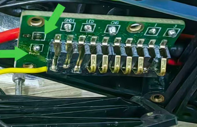
4.Solder two separate wires to extend the orange and black phase wires respectively, and cover the welding joints with heat-shrink insulation tubes for insulation protection.
5.Solder the two extended wires directly to the matching positions on the upper circuit board corresponding to the contacts on the lower circuit board one by one:
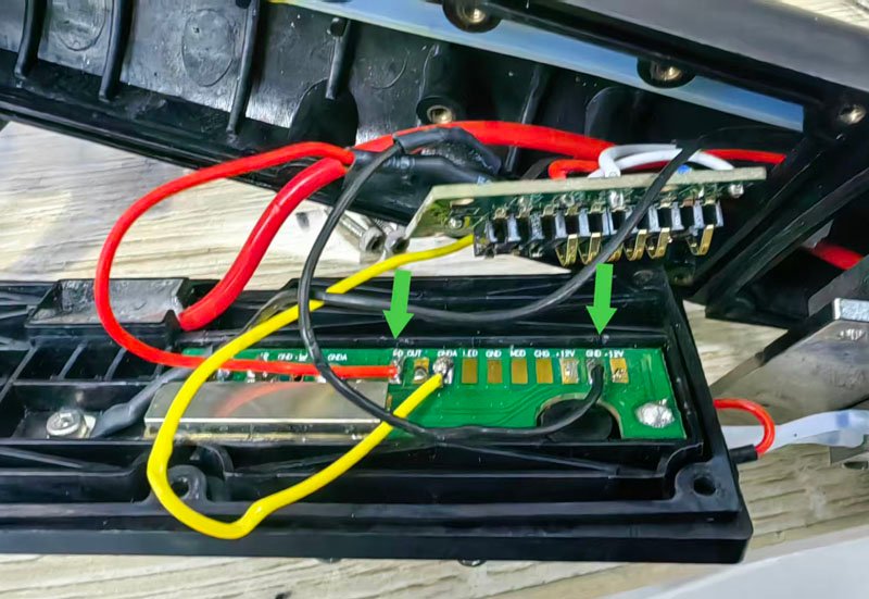
a.The black extended wire matches the 2nd contact of the lower circuit board, solder it to the position on the upper circuit board corresponding to the 2nd contact, which is where the black wire is pre-soldered in the picture;
b.The orange extended wire matches the 10th contact of the lower circuit board, solder it to the position on the upper circuit board corresponding to the 10th contact, which is where the red wire is pre-soldered in the picture. (Refer to the figure below for soldering positions. The yellow wire shown in the picture is not required and shall be ignored during circuit modification. The 9th metal contact on the lower circuit board shall be left unconnected without any wire.)
6. Reinstall the lower circuit board and fasten the fixing screws, then fit the printhead cover back. Take care not to squeeze the internal wires when installing the cover to avoid wire damage and short circuit.
Supplementary Tips
After modification, power on the equipment and check whether the phase signal is normal. The modification is completed if the signal is stable without error alarms.
Solutions for Ink Leakage of Recovery Tube
Background Note
This ink leakage issue only occurs on old-version printheads, caused by defective material of the original recovery tube. Newly produced printheads of the latest version have optimized tube materials, so this failure will not happen and no pipeline replacement is required. If ink leakage occurs on the recovery tube of old equipment, replace it with a spare ink tube of different material by following the steps below:
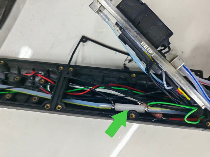
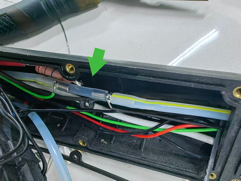
1.Disassemble the printhead and remove the original old recovery tube (See figure below).
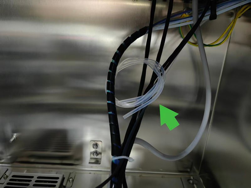
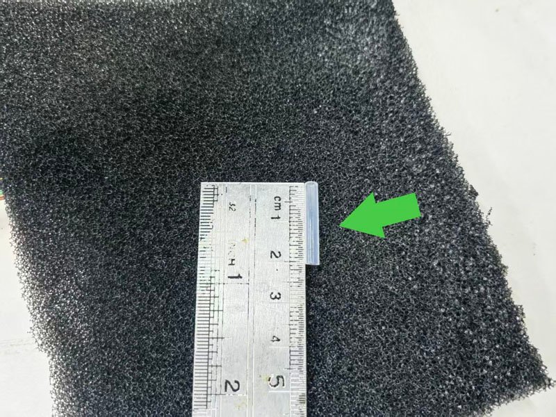
2.Open the ink compartment of the cabinet, take out the spare ink tube, and cut a 2-centimeter section from it (See figure below).
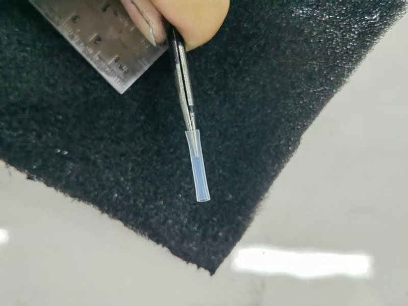
3.Use tweezers to widen the openings at both ends of the cut tube (See figure below).
4.Connect the processed spare ink tube back to the recovery pipeline (See figure below).
Supplementary Tips
After tube replacement, start the ink line and inspect all tube joints for ink seepage. The equipment can operate normally if there is no leakage and ink recovery runs smoothly.
Solution for Ink Leakage at Recovery Tube Joint of Old-Version Printheads
Applicable Note
This ink leakage issue is caused by the pipeline joint structure of old-version printheads. The joint structure of new-version printheads has been optimized, so this treatment is not required. If ink seepage or leakage occurs at the recovery tube joint on old equipment, follow the steps below:
1.Cut two small pieces of sponge adhesive tape for standby.
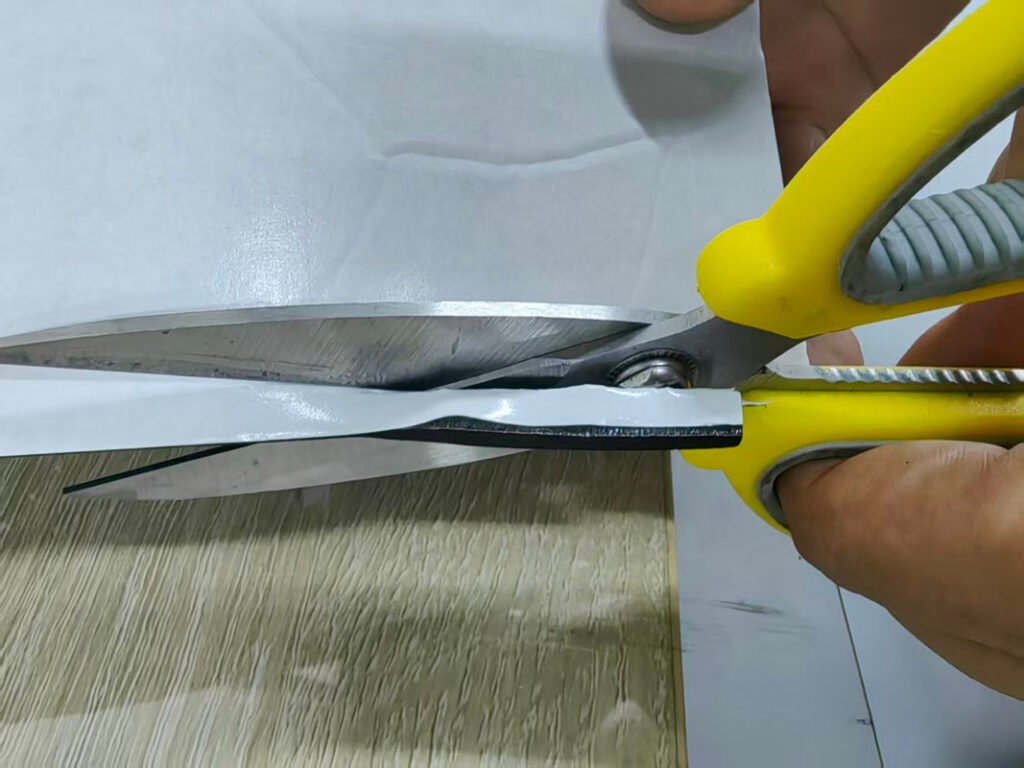
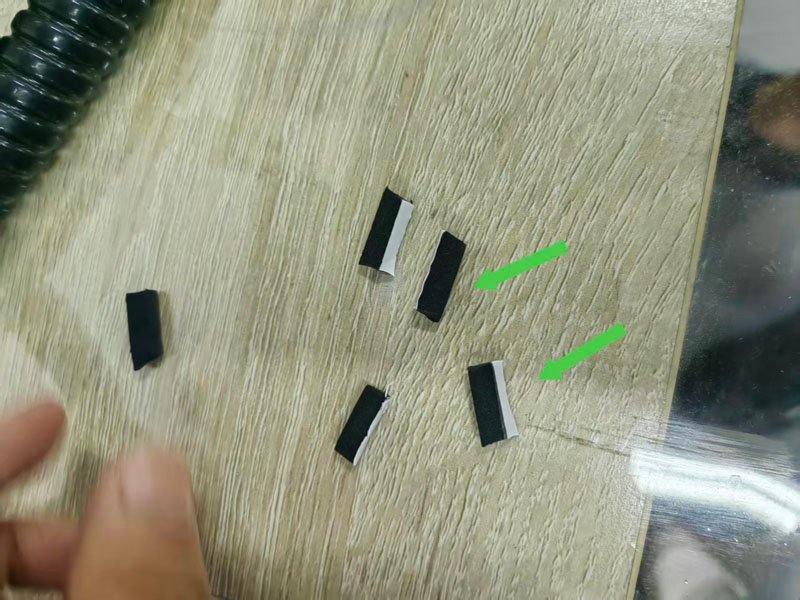
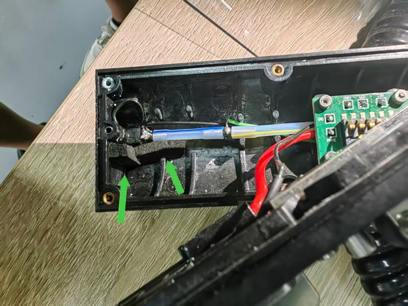
2.Remove the printhead upper cover, and attach the sponge tape to the side of the recovery tube joint for barrier protection.
3.Prepare epoxy AB glue and mix it thoroughly at a 1:1 ratio.
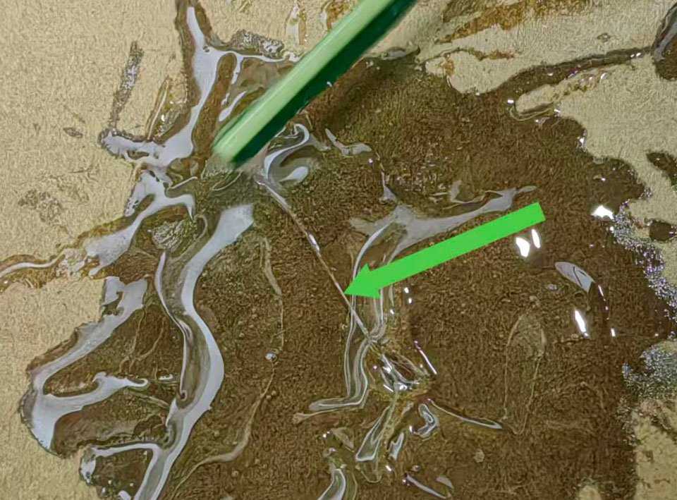
4.Apply the mixed glue evenly to the metal pipe joint, making sure the whole seam is fully filled. Take care to avoid blocking the recovery tube port with glue.
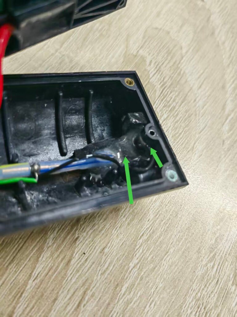
5.After gluing, place the printhead at a downward tilt and leave it to cure for 12 hours. The tilted placement prevents glue overflow to other components.
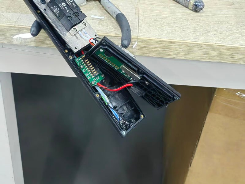
6.After 12 hours of full curing, reinstall the printhead upper cover.
Supplementary Tips
After assembly, run the ink line for a period of time and check the joint for ink seepage. The treatment is completed if there is no leakage and ink recovery runs smoothly.
How to Adjust the Ink Line Position of the Inkjet Printer
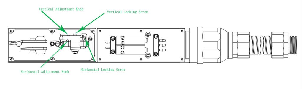
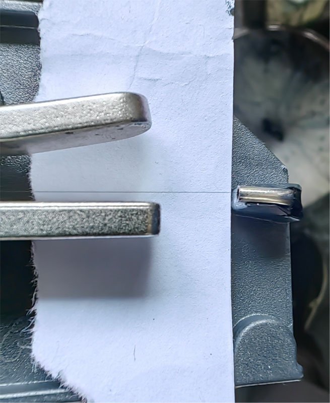
1.Horizontal Adjustment Steps
a.Loosen the horizontal locking screw.
b.Turn the horizontal adjustment knob to move the ink line into the recovery port, aligning it at the 1/4 position on the side close to the deflection plate. (See figure below)
c.Tighten the horizontal locking screw after adjustment.
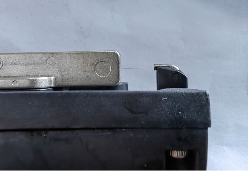
2.Vertical Adjustment Steps
a.Loosen the vertical locking screw.
b.Turn the vertical adjustment knob to center the ink line vertically in the middle of the recovery port.(See figure below)
c.Tighten the vertical locking screw after adjustment.
Supplementary Operation Tips
If the ink line deviates from the standard position, fine-tune the nozzle adjustment knob to correct the ink trajectory. After adjustment, check the ink line from both side and top views until it meets the specifications, so as to avoid faults including ink leakage, poor ink recovery and broken printed characters.
How to calibrate the position of ink line at the recovery port of small character inkjet printer?
Calibration Specifications
1.Requirement from side view
Observed from the side of the device, the ink line shall be positioned at the exact center of the recovery port to ensure stable ink recovery.
2.Requirement from top view
Observed from the top-down perspective, the ink line shall be located at the 1/4 section of the recovery port on the side close to the deflection plate.
Optional Operation Tips
If the ink line deviates from the above standard positions, you can fine-tune the corresponding adjustment knob of the nozzle to correct the ink trajectory. Recheck the position from both two perspectives after adjustment until the specifications are met, so as to prevent faults such as ink leakage, poor ink recovery and broken printing lines.
How to Select the Ink Model for Small Character Inkjet Printers?
Our small character inkjet printers support mainstream inks available on the market, with pre-stored matching viscosity curves for all common ink types built into the device.
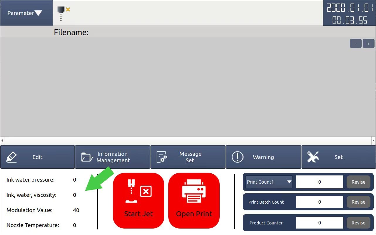
1.If you are uncertain which ink model corresponds to your consumable, do not add solvent when refilling ink for the first time. Tap the 【Start Jet】 button to activate the ink line and keep it running for several minutes. The machine will automatically detect the ink and display the measured viscosity value in the 「Ink, water, viscosity」 field on the main interface.
2.Go to the ink type setting page, set the viscosity control mode to automatic first, then select an ink type. Click the 【Parameter】 button at the top left of the screen to compare the Actual Viscosity with the Set Viscosity
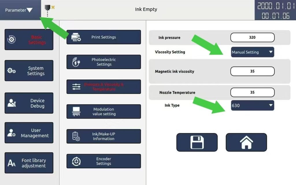
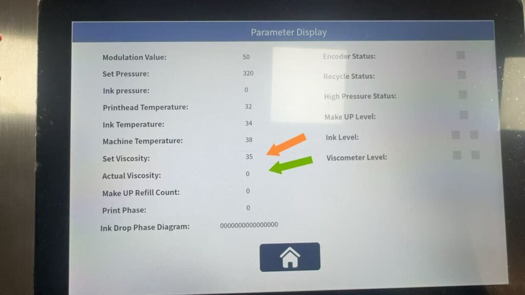
•If the two values are close, the ink model is matched successfully and the setup is finished;
•If there is a big difference between the values, choose another ink model and test again until the viscosity values match.
Can I restore factory settings?
Yes, but this will clear all parameters. Do not operate it unless necessary.
What barcodes and QR codes are supported?
Barcodes: CODE11, EAN13, CODE128, EAN14
QR Codes: QR Code, DataMatrix
What are the operation safety prohibitions?
- Do not plug or unplug cables, or open the cabinet while the power is on.
- Do not cut off the power during printing.
- Do not peer into the printhead nozzle.
- Always power off the device and wear goggles and gloves before maintenance.
What are the precautions for using ink and solvent?
- Store in a cool and well-ventilated place, keep away from fire sources, and ensure the temperature is below 35°C.
- In case of splashing onto skin or eyes, rinse immediately with plenty of clean water.
- Dispose of waste in accordance with local regulations; do not pour into sewers.
What does daily maintenance include?
Each startup and shutdown: Clean the charging electrode, high voltage deflection plate and phase probe.
Every 2000 hours: Replace the filter and dust-proof cotton.
How to handle the prompt Maintenance Period Expired?
Clean the ink system, replace the filter and dust-proof cotton, then reset the maintenance time.
How to fix blurry printing and missing characters?
- Check if the break point adjustment is normal.
- Confirm that ink viscosity and pressure are within the standard range.
- Clean the printhead and nozzle.
- Verify that the printing distance is appropriate.
How to deal with the Solvent / Ink Low Level reminder?
Open the lower compartment and add the original dedicated ink or solvent accordingly.
How to resolve the High Voltage Leakage alarm?
Cause: The printhead is damp or contaminated.
Solution: Thoroughly clean the printhead, dry it completely, then restart the device.
How to handle the Recycling Port Fault prompt?
Cause: Nozzle clogging, ink channel deflection, or ink failing to enter the collector.
Solution: Run the Nozzle Unlock or Reverse Cleaning function, clean the printhead and dry it thoroughly, then check whether the ink line is normal.
How to switch the operation language?
Supports Simplified Chinese, English, Vietnamese and Persian. Switch languages via System Settings → Language Settings. We can also add more languages according to your actual needs.
What is the function and operation method of break point adjustment?
Function: Adjust the breaking position of ink droplets to ensure clear printed characters without trailing marks.
Operation path: Basic Settings → Break Point Adjustment, modify the value (range: 0–99). Use a magnifying glass to observe the ink droplets at the charging electrode until the break point is normal.
Which parameters are not recommended to be modified arbitrarily?
The following parameters are factory default settings. Unauthorized modification may cause equipment failure or abnormal printing:
- High voltage adjustment (ultra-high voltage range, high voltage leakage value, charging value);
- Phase parameters (phase charging value, fixed phase, phase compensation compensation);
- Viscosity detection threshold and basic droplet break value.
What are the correct shutdown steps?
- Tap “Stop Ink Line” on the main interface, select normal or fast ink stop mode (wait 2–3 minutes for the procedure to complete).
- Press the power switch and wait for the display to turn off (the device is completely powered off).
- Check for ink leakage at the bottom of the printer and around the printhead; handle any leakage promptly.
What are the available printing trigger modes?
External photoelectric trigger: Automatically triggers printing when the substrate is detected by the photoelectric sensor.
Manual trigger: Configure the manual trigger function in “Message Settings” and start printing by pressing the button.
How to edit and print messages?
Tap Edit on the main interface to enter the message editing page.
Insert content: Tap Text / Barcode / QR Code / Time / Counter, enter the corresponding content and adjust parameters (font, dot matrix, spacing, etc.).
Save the file: Enter a file name, tap Save in the bottom right corner, and return to the main interface.
Start printing: Tap Print Switch (button turns green), select the trigger mode (external photoelectric trigger / manual trigger), and start printing.
What is the commissioning procedure for the first startup?
Turn on the power switch, wait for the device to finish loading and enter the main interface.
Open the lower compartment door, and pour the original ink and solvent into their corresponding tanks separately (avoid overflow).
Main Interface → Machine Settings → Ink System Operations → Clean Printhead Throat Pipe (wait 1 minute and then close).
Check for ink leakage in the ink system and printhead, and ink accumulation in the return pipe (clean and dry if any).
Tap “Start Ink Line” on the main interface, select normal or fast ink supply mode (wait 2–3 minutes to complete).
Confirm there are no fault warnings on the main screen and “Printhead Ready” is displayed; you can now edit print content.
What is the optimal installation distance for the printhead?
The distance between the printhead and the substrate is 5 mm – 40 mm, and the optimal printing distance is 10–20 mm (to ensure clear and stable printing).
What are the requirements for the power supply?
Voltage: 100–240 VAC ±10%,
Power: 120W Frequency: 50/60 Hz
Current: 3 A
Mandatory requirement: Must be reliably grounded; otherwise, the equipment may operate abnormally.
What conditions must be met for the installation environment?
Ambient temperature: 5°C – 45°C
Ambient humidity: 30% – 95% RH (relative humidity), no condensation
Space requirement: Leave at least 1 meter of space around the machine for good ventilation
Safety distance: Keep away from open flames and large electrical interference equipment (e.g., welding machines, large motors);place a fire extinguisher within 3 meters
What is the range of printable materials?
Cartons, plastic products, metal products, plates, pipes, stone materials, glass products, electronic components, auto parts, industrial chemical packaging, pharmaceutical, food and gift boxes, etc.
What are the core printing performance parameters of the Continuous Inkjet (CIJ) printer?
Nozzle specification: 60U standard configuration
Printing speed: Up to 280 meters per minute (5×5 single-line mode)
Printing height: 2 mm – 40 mm (selectable according to font dot matrix)
Printing lines: 5 lines (5×5 dot matrix), 4 lines (7×5 dot matrix)
Storage capacity: 4G standard configuration
Supported content: Text, time, date, dynamic barcodes/QR codes, custom patterns, counter variables
What is the core configuration of the printer?
It is equipped with a 10.1-inch TFT color touch screen (1280×800 resolution), a stainless-steel body, an embedded Linux secure operating system, an intelligent real-time ink viscosity detection and automatic adjustment system, and a high-performance gear pressure pump. The maintenance cycle is extended to 2000 hours or 12 months.