
Applicable Note
This abnormal phase signal failure only exists in old-version machines. The circuit design of new-version equipment has been optimized, and this modification is unnecessary.
Modification Steps
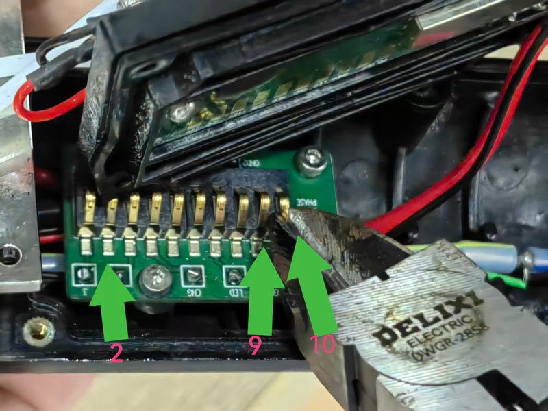
1.Disassemble the printhead and trim the 2nd, 9th and 10th metal contacts on the lower circuit board flat.
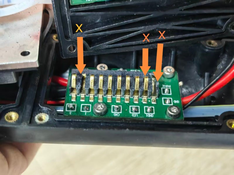
2.Unscrew all fixing screws of the lower circuit board and remove the board.
3.Use an electric soldering iron to desolder the orange and black phase signal wires from the circuit board.
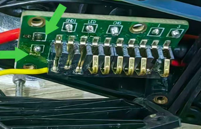
4.Solder two separate wires to extend the orange and black phase wires respectively, and cover the welding joints with heat-shrink insulation tubes for insulation protection.
5.Solder the two extended wires directly to the matching positions on the upper circuit board corresponding to the contacts on the lower circuit board one by one:
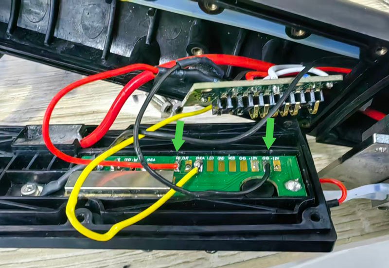
a.The black extended wire matches the 2nd contact of the lower circuit board, solder it to the position on the upper circuit board corresponding to the 2nd contact, which is where the black wire is pre-soldered in the picture;
b.The orange extended wire matches the 10th contact of the lower circuit board, solder it to the position on the upper circuit board corresponding to the 10th contact, which is where the red wire is pre-soldered in the picture. (Refer to the figure below for soldering positions. The yellow wire shown in the picture is not required and shall be ignored during circuit modification. The 9th metal contact on the lower circuit board shall be left unconnected without any wire.)
6. Reinstall the lower circuit board and fasten the fixing screws, then fit the printhead cover back. Take care not to squeeze the internal wires when installing the cover to avoid wire damage and short circuit.
Supplementary Tips
After modification, power on the equipment and check whether the phase signal is normal. The modification is completed if the signal is stable without error alarms.